Stepping into the IoT world: my experience with ESPHome
· 2,179 words · 11 minutes reading time
I have a first world problem: I live in a typical 2-storey terraced house in England. I know, that doesn't sound like a problem, but let me tell you that if I want to turn on or off the lights in the hall I have to use the switch downstairs. In a country where winters are really dark and staircases are quite steep (seriously, I'm not joking), I find myself using my smartphone as a torch quite often at night.
I thought that a smart switch could be a solution. There are small devices that can be hidden inside the ceiling roses, allowing the existing light switches to keep working as usual. They are also cheap, compared to other alternatives, such as smart bulbs, so, this looks like a winner.
Now, I want to have some control over the firmware running in such a device, considering that it will be connected to my home network. However, that's not a major concern for the average Joe, so I ended up buying 5 units of the cheapest smart switch on Amazon and let a future version of me figure out what can be done with them.
The smart switch
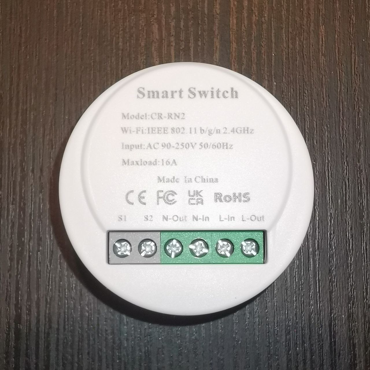
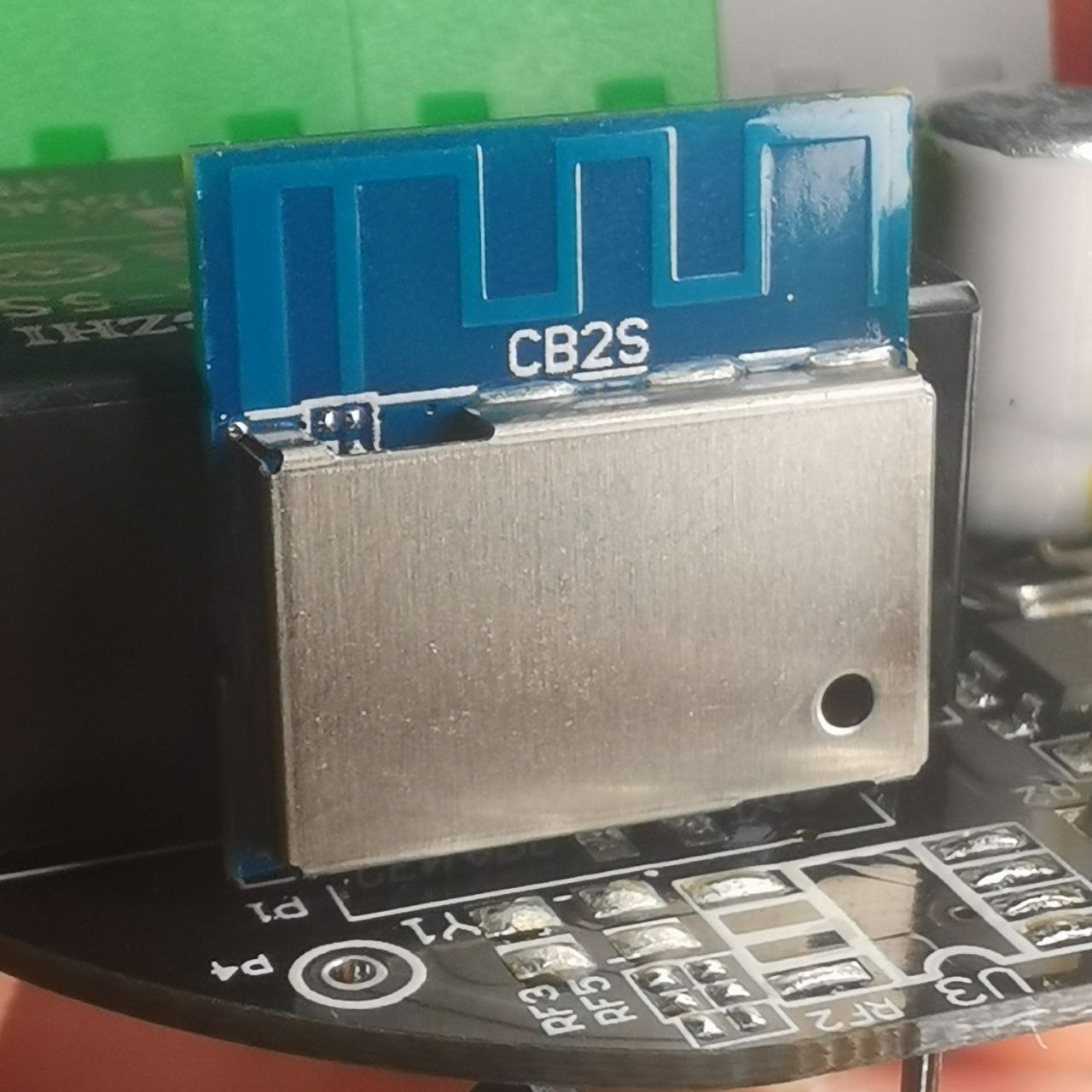
Right out of the box, I decided to open one of the smart switches just to check what's inside. To my surprise, I discovered that the circuit is controlled by a CB2S module, a Wi-Fi module with a BK7231N chip. This is not the famous ESP module for which there are so many projects out there but it is pretty standard and a decent amount of information about it can be found online.
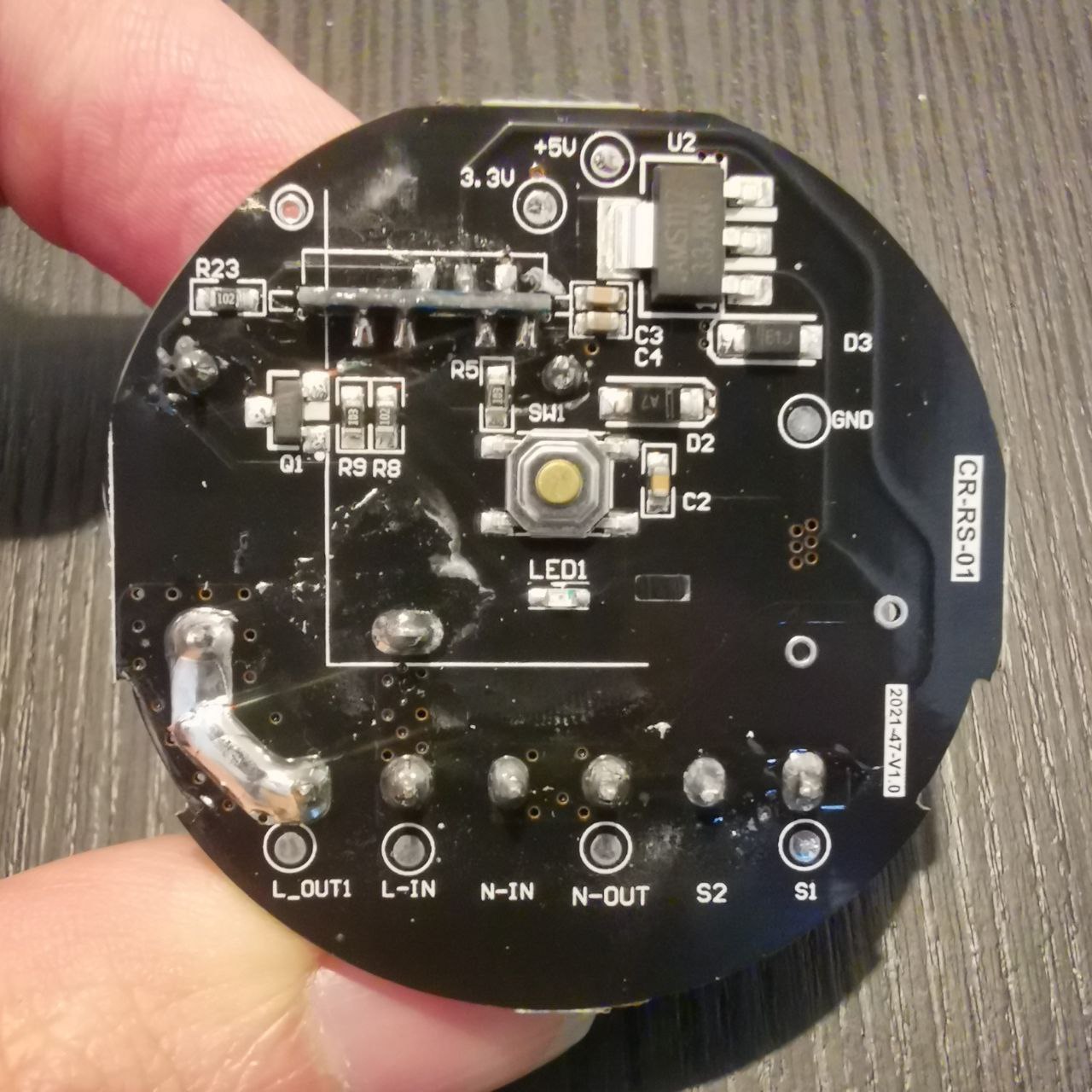
The printed circuit board (PCB) comes with a button, which I will ignore as the device will be hidden, and an LED connected to one of the pins in the CB2S module, which will be handy later on. Other than that, the PCB has 2 terminals for the input line and neutral wires, 2 outputs that will be connected to the ceiling lamps and 2 terminals called S1 and S2 for connecting the existing light switch.
The most important thing about the CB2S module is that it can be reprogrammed as it counts with a serial interface with RX/TX pins for it. So, in theory, I can change the default firmware with an open-source alternative. This alternative will be ESPHome.
Why ESPHome?
ESPHome is an open-source firmware for different types of microcontrollers (despite its name), including the BK72xx family through the LibreTiny platform. It is well-integrated with Home Assistant (the most popular open-source software for home automation) through its API and can be configured entirely using YAML files.
The configuration files are used to compile a minimal image of the firmware containing only the required components of the entire ESPHome suite.
Alternatively to ESPHome, I considered Tasmota. This open-source firmware comes in a single image that can be configured using a web app which is served by the device itself. While the web app might be easier to use than the configuration files for ESPHome, the integration with Home Assistant uses MQTT, so an additional MQTT broker has to be configured.
However, Tasmota doesn't support the BK72xx chips. There is a similar project called OpenBeken, but this project doesn't have as much acceptance as Tasmota or ESPHome. After giving OpenBeken a try without fully enjoying it, I ended up going with the most popular option available for the module in my smart switch, ESPHome, and I don't regret it.
Setting up ESPHome
ESPHome comes with a handy CLI and a dashboard that can be used for compiling firmware images and updating devices over the air (OTA updates). Considering that the dashboard is just a web app wrapping the CLI, I'll be using the latter.
Both the CLI and the dashboard are implemented in Python and can be installed using pip, but I'll rely on a Docker image instead, so everything is installed inside a container that I can drop at any moment. This is the content of the compose.yaml file:
version: '3'
services:
  esphome:
    container_name: esphome
    image: ghcr.io/esphome/esphome
    volumes:
      - ./config:/config
      - /etc/localtime:/etc/localtime:ro
    privileged: true
    network_mode: host
    env_file:
      - ./secrets.env
The environment variables in ./secrets.env are USERNAME and PASSWORD, the credentials for the dashboard. The configuration files will be stored in ./config/. For now, let's execute docker compose up -d so the container is created and started.
One good thing about ESPHome is that it supports templates that can be reused for multiple devices (or nodes, as they call them). As I'm only using one type of smart switch, I'll create a single template in ./config/switch_template.yaml with the following content:
esphome:
  name: "${snake_node_name}"

bk72xx:
  board: cb2s

logger:

api:
  encryption:
    key: !secret api_key

ota:
  password: !secret node_password

wifi:
  ssid: !secret wifi_ssid
  password: !secret wifi_password

  ap:
    ssid: "${node_name} Fallback Hotspot"
    password: !secret fallback_ap_password

captive_portal:

switch:
  - platform: gpio
    name: "${node_name}"
    id: internal_switch
    pin: P24
    on_turn_on:
      - output.turn_on: led
    on_turn_off:
      - output.turn_off: led

binary_sensor:
  - platform: gpio
    id: external_switch
    pin:
      number: P7
      mode: INPUT_PULLUP
    filters:
     - delayed_on_off: 100ms
    on_state:
      then:
       - switch.toggle: internal_switch

output:
  - platform: gpio
    id: led
    pin: P8
Let's go through the template. First, there are 2 substitution variables, node_name and snake_node_name, that will be replaced with the name of each room and its snake-case version. There are also some secret values that will be common for all the nodes. These secrets are referenced by the keyword !secret followed by a variable name. The secret values will be stored in ./config/secrets.yaml.
Now that the format of the template is clear, I'll go through each section in the template:
-
The first lines define the name of the node and the type of microcontroller that we are targeting.
-
The following sections are independent of the board and configure some interesting features in ESPHome. Basically, I'm enabling a logger for the events in the node, the API integration with Home Assistant (given a 32-bit base64 API key, which can generated through ESPHome doc page), the OTA updates (providing a password that will be used by ESPHome for future updates), the Wi-Fi credentials for my home network and, if the node fails to connect to it, the details for a fallback hotspot so the node becomes an access point with a captive portal.
-
The last 3 sections define the particular behaviour of the smart switch:
- There is a
switchcontrolling the relay in the PCB which is connected to pinP24in the CB2S module. - There is also an
outputfor the LED in the PCB which is connected to pinP8in the CB2S module. The LED will indicate whether the relay is on or off as configured in theswitchsection. This is useful for checking if the board is working correctly. - And just in the middle we have the
binary_sensorconfiguration, which will determine if the circuit connected toS1andS2in the PCB is open or closed. AsS2is connected to ground andS1is connected to pinP7, we have to use a pull-up resistor to read a logic value from that sensor. That's achieved with theINPUT_PULLUPmode. The rest of the configuration is for toggling the relay when there is a change in the value read from the pin after a debouncing period of 100ms.
- There is a
Using this template is now as easy as creating a YAML file (e.g. staircase.yaml) replacing the substitution variables like this:
substitutions:
  snake_node_name: "staircase"
  node_name: "Staircase"

<<: !include switch_template.yaml
All I need to do is to compile and install the firmware.
Flashing the firmware
Let's connect to the docker container that we started previously with docker exec -it esphome bash. We are now in a bash session inside the container and we should land in /config, a directory linked to ./config in the host, containing the previously defined configuration files.
By executing the command esphome compile staircase.yaml, the configuration is parsed and validated, the source code for the firmware is generated, the required dependencies are downloaded and installed inside the container and the firmware is finally compiled!
But where is it? Let's take a look inside the following directory:
cd /config/.esphome/build/staircase/.pioenvs/staircase/
There are a bunch of files and directories but we only care about the ones called image_bk7231n_app.*. The information about those files is in firmware.json:
# cat firmware.json
[
	{
		"title": "Cloudcutter Image",
		"description": "UG Image for flashing with tuya-cloudcutter",
		"filename": "image_bk7231n_app.ota.ug.bin",
		"offset": null,
		"public": true
	},
	{
		"title": "Beken OTA Image",
		"description": "For flashing using Beken or OpenBeken OTA",
		"filename": "image_bk7231n_app.ota.rbl",
		"offset": null,
		"public": true
	},
	{
		"title": "Beken Application Image",
		"description": "For flashing directly",
		"filename": "image_bk7231n_app.0x011000.rbl",
		"offset": 69632,
		"public": true
	},
	{
		"title": "Beken CRC/UA App",
		"description": null,
		"filename": "image_bk7231n_app.0x011000.crc",
		"offset": 69632,
		"public": false
	},
	{
		"title": "Beken Application RBL Header",
		"description": null,
		"filename": "image_bk7231n_app.0x129F0A.rblh",
		"offset": 1220362,
		"public": false
	}
]
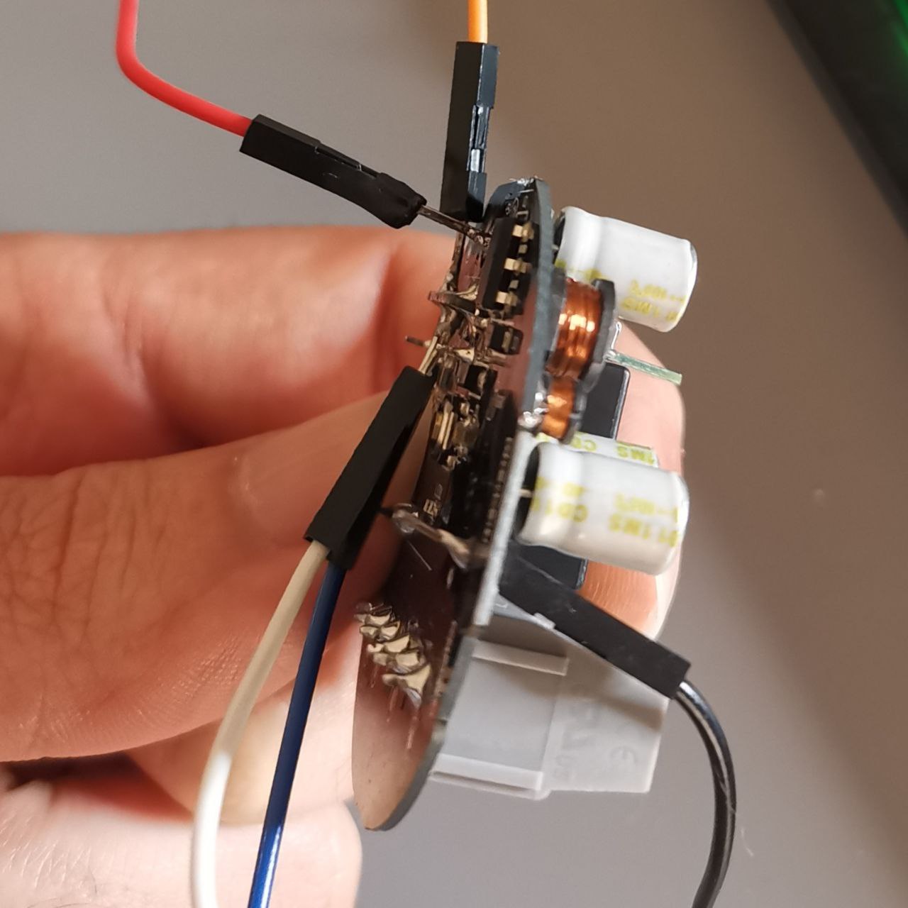
Now, at this point of the project, I decided that I wanted to have fun and flash the image directly into the board by soldering some jump wires to the pins in the CB2S module and connecting them to the UART in my Raspberry Pi.
Yes, I'm not kidding and I have some arguments for that. First, I don't want to install any app recommended by the manufacturer nor rely on the pre-installed firmware. I won't give it a chance. And secondly, while the previous configuration files work, they are the result of a process of trial and error, which, of course, is easier when the PCB is connected to a 3.3v source rather than using 230v.
So I soldered 5 wires to the board, 2 to the 3.3v and ground terminals in the PCB, another 2 to the RX and TX pins in the CB2S module, which can be used to communicate with the module using a serial protocol, and a last wire to the CEN pin, so the board can be reset and the serial communication can be established when connected to the ground for a moment.
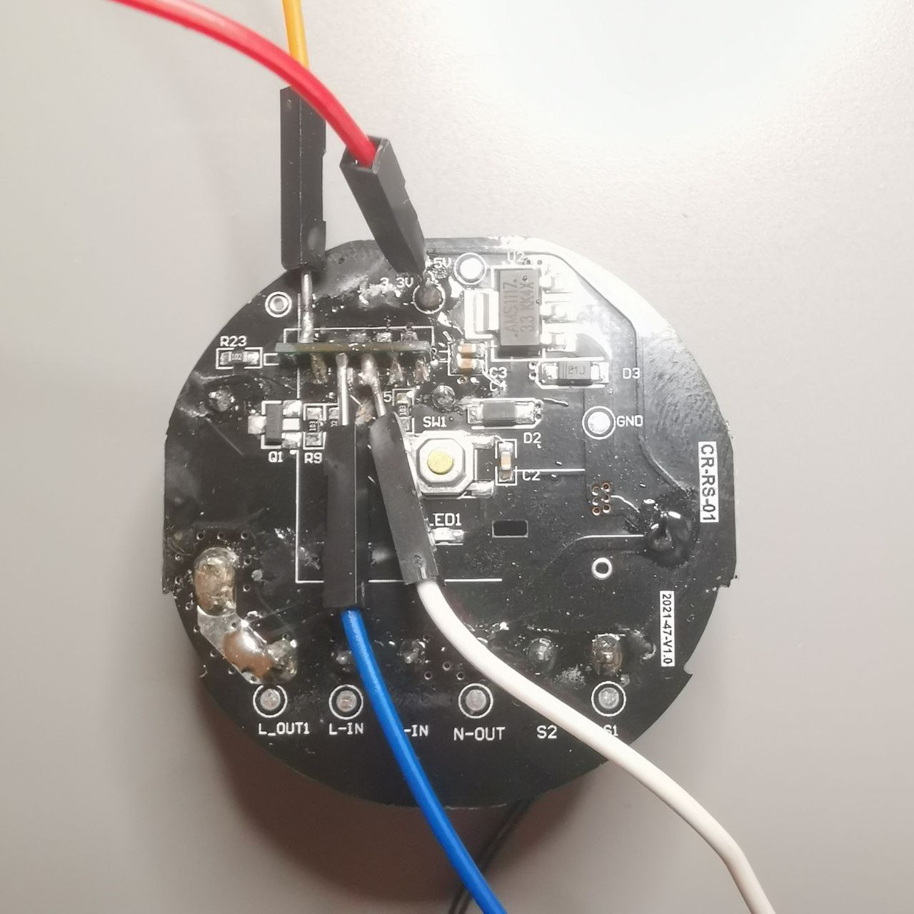
We are almost there. Now, the CB2S module can be connected to the Raspberry Pi so its UART can be leveraged for programming the board instead of a serial programmer.
There are multiple options for flashing the firmware through this method. I decided to use hid_download_py as it was the first option that I found while considering OpenBeken and it works fine for ESPHome too. There are some alternatives listed in LibreTiny's website (ltchiptool, the recommended one, includes a GUI) but as I said, I stuck to what worked fine for me before I knew of ESPHome.
So, I download the repo into my Raspberry Pi and, following the installation guide, I execute
sudo apt install python3-hid python3-serial python3-tqdm
python3 setup.py install --user
After that, I copy the image into the repo's directory and, while the board is connected to the Raspberry Pi, I execute
# Write image starting at memory address 0x11000 (flash memory containing
# the original firmware) using the ttyAMA0 device (UART)
sudo python3 uartprogram image_bk7231n_app.0x011000.rbl -d /dev/ttyAMA0 -w -s 0x11000 -u
Finally, I connect the wire soldered to CEN to ground for a second and... The firmware was flashed successfully!
Integration with Home Assistant
At this point, I'm just missing the easiest steps of the journey. I go ahead and install Home Assistant using the following Docker compose configuration:
version: '3'
services:
  homeassistant:
    container_name: homeassistant
    image: "ghcr.io/home-assistant/home-assistant:stable"
    volumes:
      - ./config:/config
      - /etc/localtime:/etc/localtime:ro
    restart: unless-stopped
    privileged: true
    network_mode: host
In port 8123, Home Assistant's web app is available. I follow the sign-up form and as part of the last step, it already detects the available ESPHome nodes. I go to Settings > Devices & Services and I can see the smart switch for the staircase.
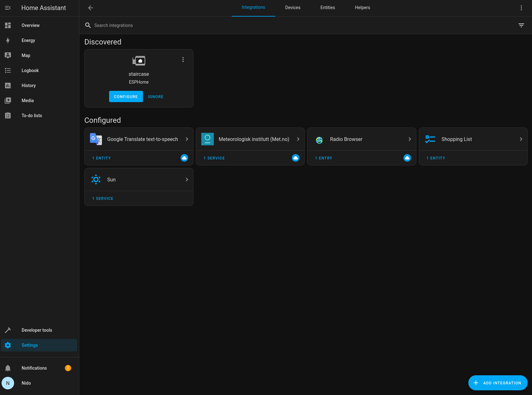
I click on the configure button and I'm asked for the API key that I added to the ESPHome configuration. And that's all! I can already play with Home Assistant and use my smart switch from the browser. It's time to remove the soldered wires and install the smart switch.
Conclusion
ESPHome is a robust alternative to the pre-installed firmware in smart switches and other types of IoT devices used for home automation, as long as their microcontrollers are supported. I like how well integrated it is with Home Assistant which I consider a great platform for orchestrating this type of devices.
Now I can turn the lights on from my smartphone instead of using it as a torch. And soon, I hope I can ask Alexa for it, as I found that there is a way to connect her to Home Assistant. But that's for a different post.
All the configuration files can be found in this repo. Enjoy!